

How are neodymium magnets made?
In the common sintered route, manufacturers turn an alloy into powder, orient and compact that powder, then use heat to produce a dense body. Machining establishes the geometry, a protective finish covers the surface, and magnetization gives the part its intended external field. Inspection connects those operations to the finished requirement.
These six stages describe sintered NdFeB. Mining, rare-earth separation and metal refining take place upstream, and the businesses handling those activities may differ from the finished-magnet manufacturer.[6] Bonded and hot-deformed NdFeB follow different routes, outlined after the six stages.

1. Alloy preparation and powder milling
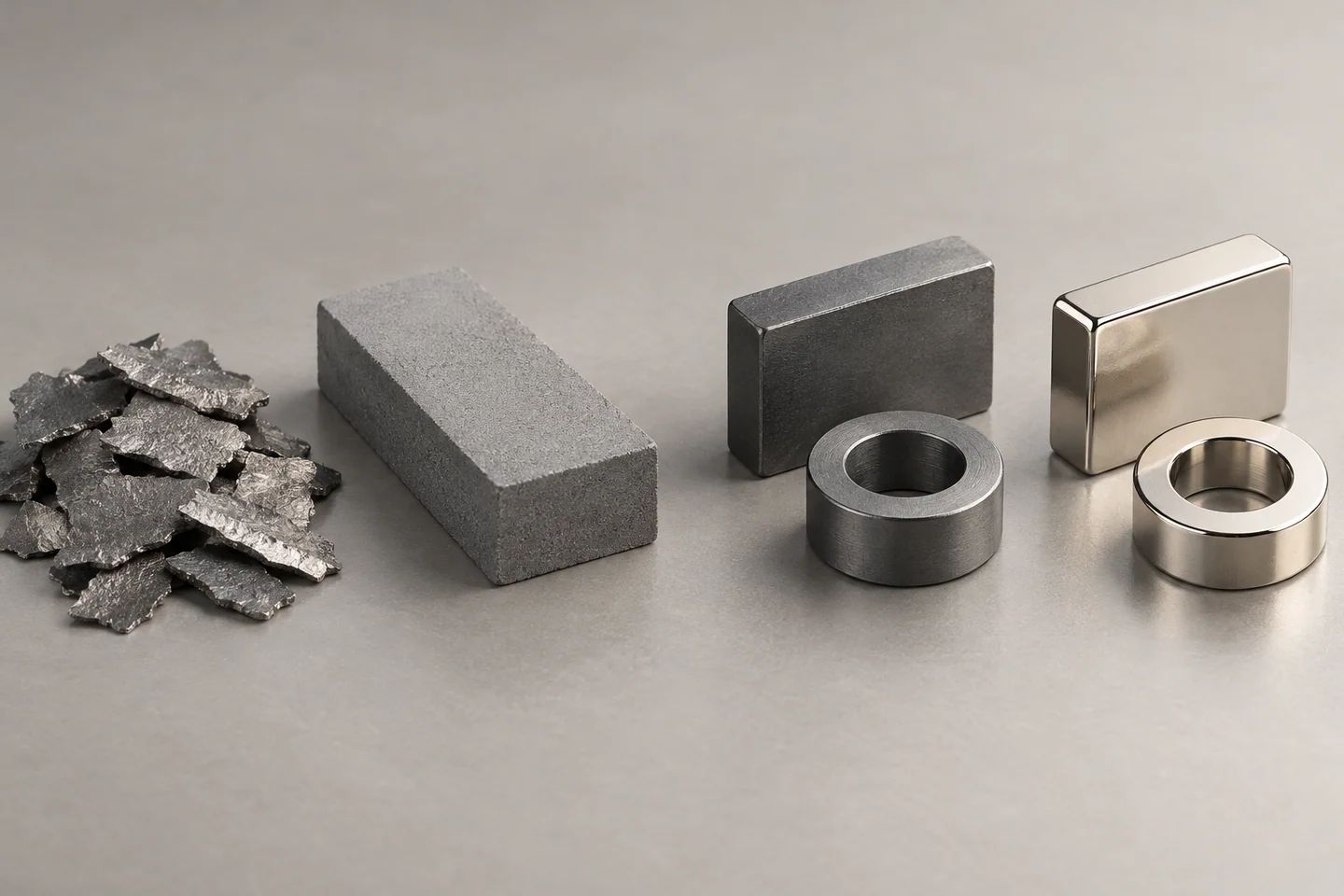
Selected raw materials are melted together. Strip casting cools the melt into thin flakes, giving the next stages a consistent alloy feedstock. Hydrogen decrepitation breaks the brittle flakes down; milling reduces the fragments to fine powder. Oxygen exposure must be controlled because the fine material is reactive.[2]
Powder allows the particles to be oriented before they become a dense body. Particle-size distribution and impurity control affect the resulting magnetic properties.[5] Specifying the alloy composition therefore addresses only part of the manufacturing requirement.
2. Magnetic alignment and pressing
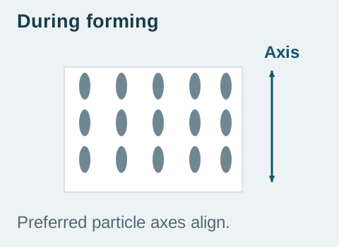
In anisotropic sintered NdFeB, an applied field aligns the particles' preferred magnetic directions. Pressing holds that arrangement in a shaped compact. “Anisotropic” means the material's magnetic behaviour depends on direction. The compact is an intermediate body, not yet a finished machined part.[1]
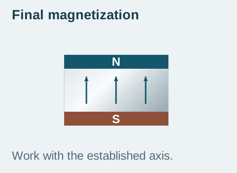
This orientation constrains the component's intended magnetization direction. The final magnetizing operation happens later and must work with the established preferred axis. When an aligned blank is cut into smaller parts, its orientation still determines how their intended pole direction relates to the cut faces.[2] Show the required direction before selecting the blank and cutting layout. The magnetization-direction guide gives drawing examples.
3. Sintering and heat treatment
Sintering heats the pressed compact under controlled conditions so it becomes a dense body. The process must reduce porosity while controlling grain growth. The grains are the small crystalline regions within the material. Excessive growth or remaining open pores can undermine the intended properties and resistance to deterioration.[3]
A subsequent heat treatment develops coercivity and the magnetic response. Coercivity describes resistance to demagnetization by an opposing field. Densification and heat treatment therefore answer different needs: forming a sound body and establishing the required magnetic behaviour.
The body shrinks during sintering, and shrinkage can differ along and across the alignment direction. Its surfaces still need finishing to meet the drawing. A universal enlargement percentage would not reliably convert a finished drawing into a pressing tool.[3]
4. Cutting and grinding to shape
Hard, brittle sintered material is commonly sliced and ground with suitable abrasives; electrical discharge machining can produce some complex profiles. Holes, slots and thin sections increase handling and finishing difficulty. Machining changes geometry without resetting the material's preferred magnetic direction.[1]
For a ring, one possible route is a hollow cylindrical form sliced into washers and finished to size. For a block, a larger aligned blank can yield several smaller parts. The choice between forming near the required shape and removing material from a larger blank depends on geometry, quantity and tooling.[1]
5. Edge finishing and protective coating
Sharp machined edges are vulnerable to chips and uneven coating coverage. Edge finishing helps prepare a more consistent surface. NdFeB is corrosion-sensitive, so a finish is selected against the intended environment and component design.[3]
The finish becomes part of the delivered geometry. A bore or pocket fit should therefore be defined on the coated component. Temperature and exposure are coating-selection inputs, alongside assembly requirements.[2] The coating guide compares finishes; the nickel guide explains their effect on dimensions.
6. Magnetization and inspection
A magnetizing fixture applies a strong field to establish the intended magnetic state. Some designs are magnetized after assembly to simplify handling; fixture access and the assembly affect that choice.[1] A stronger pulse cannot turn a lower-grade material into a higher grade.
Finished-part inspection covers dimensions, appearance and magnetic results.[8] Choose the magnetic measurement for the requirement: a field measurement at one point, the part's overall magnetic moment and its response in an assembly answer different questions.[9]
| Check | What it establishes |
|---|---|
| Finished dimensions and appearance | Whether the coated part meets the drawing and agreed surface criteria. |
| Material magnetic properties | Whether representative material meets the specified properties at the stated temperature. |
| Field at a point | The field at a defined probe position, distance and axis. |
| Magnetic moment | The part's overall magnetic dipole strength, measured with a defined method and orientation. |
| Assembly force or response | Performance with the specified counterpart, gap and load direction or sensor position. |
What each check establishes
Finished dimensions and appearance
- What it establishes
- Whether the coated part meets the drawing and agreed surface criteria.
Material magnetic properties
- What it establishes
- Whether representative material meets the specified properties at the stated temperature.
Field at a point
- What it establishes
- The field at a defined probe position, distance and axis.
Magnetic moment
- What it establishes
- The part's overall magnetic dipole strength, measured with a defined method and orientation.
Assembly force or response
- What it establishes
- Performance with the specified counterpart, gap and load direction or sensor position.
Match each result to its sample and test conditions. The inspection guide explains measurement and acceptance records in more detail.
Example: the ring fits, but the sensor response is wrong
Illustrative investigation of an axial sensor ring
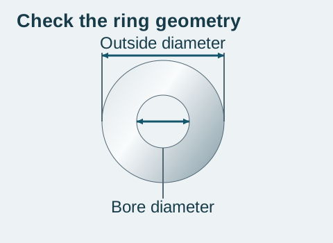
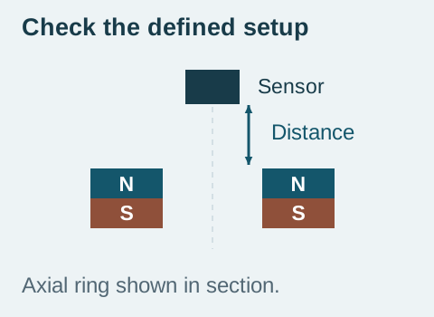
Assume a sintered ring meets its finished outside diameter, bore and thickness requirements. The drawing calls for poles on the two flat faces, but the sensor response falls outside the agreed limit.
- Confirm the test uses the specified sensor position, ring orientation and temperature. Correct a mismatched setup before comparing results.
- Check the pole arrangement against the drawing. If the poles are wrong, review both the blank's alignment relative to the machined faces and the final magnetizing operation.
- If the poles and setup match, review the material identity and magnetic inspection records. Powder preparation, heat treatment and magnetization affect the result; further evidence is needed to identify a process problem.
Passing the dimensional checks establishes the ring's geometry. It does not establish the pole arrangement or the field at the sensor. Keep the sample and test record so the next check can address the unresolved magnetic requirement; a low reading alone does not justify changing grade or magnetizing pulse.
How do bonded and hot-deformed magnets differ?
Bonded magnets combine magnetic powder with a polymer binder. Compression bonding presses the mixture and cures the binder as required; injection molding shapes a thermoplastic compound and cools it. These routes produce a composite rather than the dense body made by the sintered sequence.[7]
Bonded material can be isotropic or anisotropic. Magnequench describes both powder types, so “bonded” alone does not tell you the preferred direction or magnetic arrangement.[4] The compound and binder also need identification; a sintered N-grade label is insufficient.
Hot deformation is another route: rapidly solidified material is densified and mechanically textured at elevated temperature. Its orientation develops through deformation rather than simply repeating the powder-alignment stage above.[7] Use the sintered-versus-bonded comparison for selection tradeoffs. Other families, including SmCo, ferrite and Alnico, have their own processing details; the material-family guide distinguishes their names.
How does the process affect magnetic properties?
Composition, alignment and microstructure work together. Grain boundaries, the regions between crystalline grains, can be engineered to affect resistance to demagnetization. TDK's HAL example introduces dysprosium preferentially near these regions through diffusion, improving coercivity while limiting bulk substitution.[5] This is one manufacturer's process, not a requirement for every grade.
The grade describes specified material properties. A more demanding grade still needs the right orientation, finished geometry and protection for the assembly. Improving resistance to demagnetization addresses a different requirement from making a bore fit or correcting the pole arrangement.
What should a designer decide before manufacture?
- Show the magnetic axis or pole pattern relative to the component. It affects the choice of aligned material and cutting layout.
- Mark the finished, coated dimensions that govern fit, including holes and mating faces. Identify which tolerances are essential to the assembly.
- Describe exposure and any gluing or curing process when selecting the protective finish.
- Define the required result and the conditions for checking it. A sensor reading, a holding-force requirement and a material grade need different evidence.
Include the order quantity with the drawing so the forming and machining route can be discussed.[1] Nike Industrial Trading is the trading contact through the custom requirements page. The supply and quality guide explains how to connect the agreed drawing with inspection records.
Explore this requirement
Technical sources
Read each source with its stated material, test conditions and publication scope.
- Arnold Magnetic Technologies — Magnet Manufacturing ProcessParticle alignment, shaping, finishing and final magnetization.
- SM Magnetics — Making a Neodymium MagnetIllustrative manufacturing sequence with application-dependent coating and finishing.
- Cui et al. (2022) — Manufacturing Processes, Part IJOM process review; sintering, shrinkage, machining and coatings.
- Magnequench — About Bonded Neo PowdersOriginal maker's isotropic/anisotropic powder and binder-route explanation.
- TDK — HAL Production ProcessMicrostructure, impurity control and the HAL grain-boundary diffusion process.
- U.S. DOE (2022) — Rare Earth Permanent Magnets Supply Chain AssessmentManufacturing stages within the rare-earth magnet supply chain, as described in the 2022 assessment.
- Cui et al. (2022) — Manufacturing Processes, Part IIBonded forming, hot pressing and hot-deformation mechanisms.
- ULVAC (2026) — Nd Magnet Manufacturing Process, slide 15Representative manufacturing stages and final inspection categories on slide 15.
- Magnetic Testing ServicesDifferent methods for measuring magnetic properties and finished-part performance.