
Define an axis and the pole location
Magnetization direction describes the orientation of the magnetization within the part. Polarity identifies which end or surface region is N or S. Two parts may have the same magnetic axis but opposite required pole faces.
For a symmetric part used alone, exchanging the ends may not change its function. In a paired closure, motor or sensor assembly, it can matter greatly. Tie a pole requirement to a visible reference face, a drawing view or an assembly datum, rather than saying only “north facing up”.
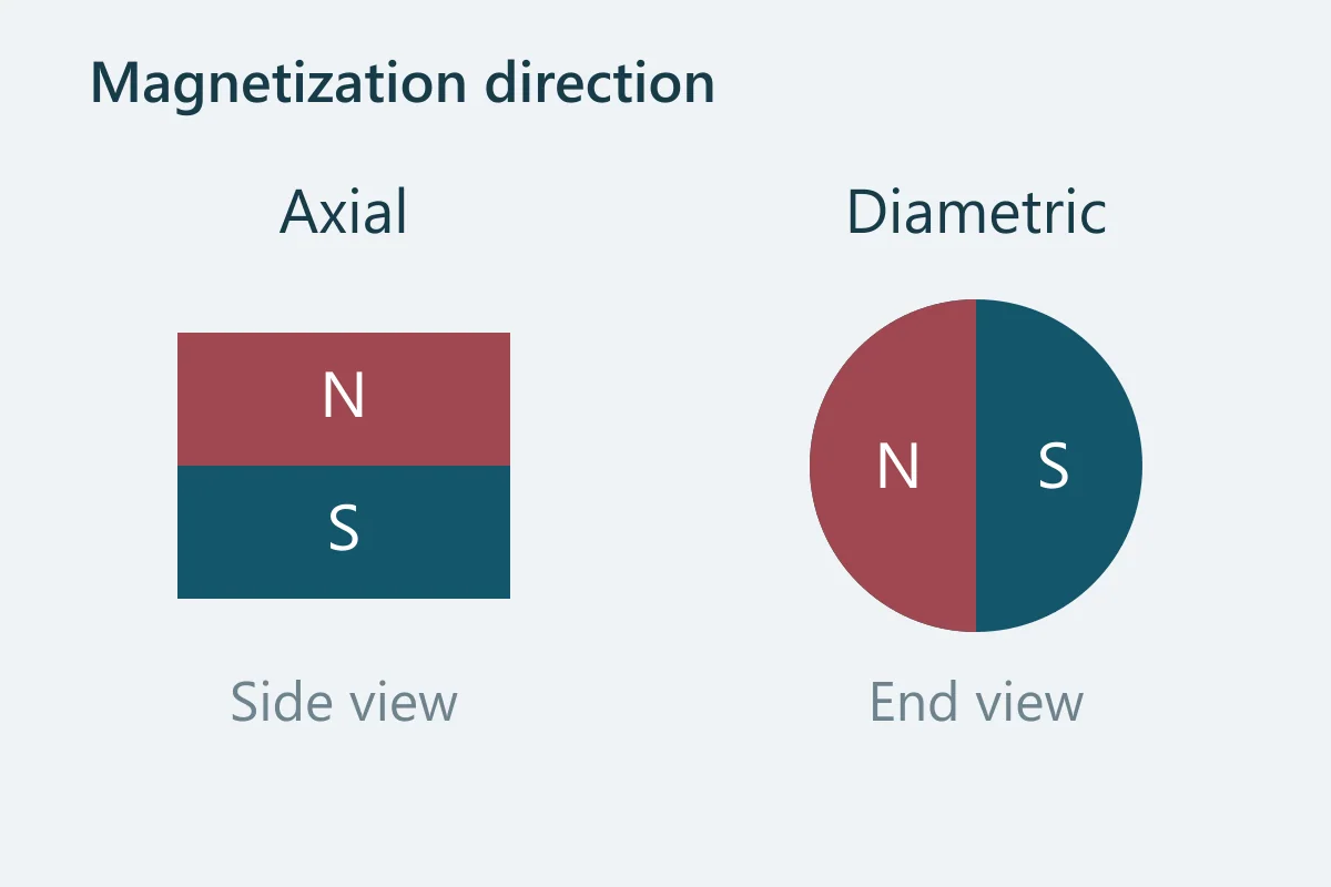
In these examples, axial magnetization follows the cylinder axis; diametric magnetization runs across the diameter. Their outward appearance does not reveal the difference.[1] [3]
Relate the description to the shape
| Geometry | Description | What to clarify |
|---|---|---|
| Disc or cylinder | Axial or diametric | End or angular reference where polarity matters |
| Block | Through a named dimension | Which physical faces that dimension connects |
| Ring | Axial, diametric, radial or a specified pattern | Inner/outer polarity, angular datum or pole pattern |
| Arc segment | Parallel, radial, axial or another agreed direction | Vector direction, pole surfaces and relationship to the assembly axis |
| Multipole component | A defined number and arrangement of poles | Pole pitch, sequence, reference angle and field requirement |
Common direction descriptions and missing information
Disc or cylinder
- Description
- Axial or diametric
- What to clarify
- End or angular reference where polarity matters
Block
- Description
- Through a named dimension
- What to clarify
- Which physical faces that dimension connects
Ring
- Description
- Axial, diametric, radial or a specified pattern
- What to clarify
- Inner/outer polarity, angular datum or pole pattern
Arc segment
- Description
- Parallel, radial, axial or another agreed direction
- What to clarify
- Vector direction, pole surfaces and relationship to the assembly axis
Multipole component
- Description
- A defined number and arrangement of poles
- What to clarify
- Pole pitch, sequence, reference angle and field requirement
A straight-axis arc can present opposite pole regions toward its inside and outside faces without being truly radially oriented. Likewise, diametric magnetization across a ring is not the same as magnetization from the bore to the outer cylindrical surface.[2] [1]
Material orientation constrains the final magnetizing operation
Common anisotropic sintered NdFeB has a preferred direction established during manufacturing. The final magnetizing operation must be compatible with it. Reversing polarity along an established axis is a different operation from asking an existing anisotropic part to magnetize efficiently along a different axis.
Bonded does not automatically mean isotropic. There are both isotropic and anisotropic bonded systems, and anisotropic material needs an orientation process. Complex pole patterns also need suitable material, magnetizing equipment and validated geometry.[2] [4]
A supplier’s catalogue convention of calling the last dimension “thickness” is useful within that catalogue, but it is not a substitute for a customer drawing. A long bar can be magnetized along its long dimension even if someone informally calls a shorter dimension its thickness.
Put the requirement and verification on the drawing
- Show the part in a reference view and mark the magnetic axis.
- Identify the required N or S face. If an arrow is used, explicitly state its polarity convention.
- Connect the marking to a part datum or assembly reference.
- For a set, give the pole sequence and quantities of each polarity.
- Define whether acceptance concerns pole location, magnetization angle, field at a point or a measured multipole pattern.
For sensor applications, include the sensor orientation and working gap. For a field measurement, define the probe position, direction and fixture. Product and material characteristics require different measurement arrangements; manufacturer guidance emphasizes agreeing these conditions in advance.[5]
Send the drawing even if some choices are open. Describe the function rather than guessing a direction from the shape.
Technical sources
Source material has its own scope and conditions. These references explain technical choices; they are not evidence of our stock, certifications or supplied products.