

The magnet's role in a permanent-magnet motor
In a permanent-magnet motor, NdFeB can supply the permanent magnetic field that interacts with the energized electromagnetic system to produce torque. Its high magnetic energy density makes it relevant where the design must fit useful magnetic performance into a limited space. Other permanent-magnet materials are also used, and many electric-motor designs do not use permanent magnets at all.[1] [2]
The cover shows one simplified surface-magnet rotor arrangement: magnets on the rotor, a surrounding stator and an air gap between them. Interior-magnet and other arrangements place the magnets differently. A generic “AC motor” description does not identify the magnet topology, geometry or grade.
For a segment-shaped part, the arc magnet guide connects the radii, included angle and axial length to a drawing. A material inquiry can begin with the sintered NdFeB specification guide. Neither the shape name nor the material name completes the motor design.
Balance magnetic performance with operating conditions
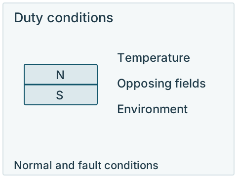
Grade selection involves the required output at the operating point, the available magnet volume and the conditions the magnet must survive. The highest room-temperature energy-product class is not automatically the most suitable choice when temperature, opposing fields or retention dominate the application.[1] [2] [5]
Keep the records connected
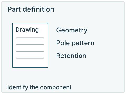
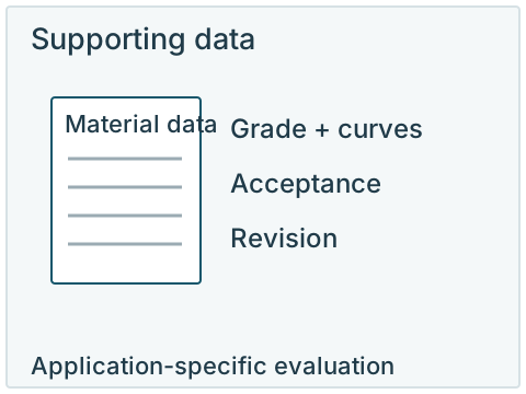
Use the same component reference for the drawing, material curves and acceptance requirements. A grade name alone cannot establish the motor’s demagnetization margin.
Open larger diagram| Design input | Information needed | Decision it informs |
|---|---|---|
| Geometry and magnetic axis | Part drawing, assembly position, pole pattern and available space. | Component shape and orientation. |
| Magnetic operating conditions | Applicable material curves, circuit conditions and opposing fields. | Useful output and demagnetization margin. |
| Temperature duty | Magnet temperature, peaks, exposure time and cycles. | Grade data and hot-state evaluation. |
| Environment and retention | Moisture or chemical exposure, coating, bonding and mechanical support. | Surface and assembly requirements. |
| Supply and acceptance | Quantity, drawing revision, required checks and documents. | A comparable component inquiry and approval basis. |
Connect each design input to a specification
Geometry and magnetic axis
- Information needed
- Part drawing, assembly position, pole pattern and available space.
- Decision it informs
- Component shape and orientation.
Magnetic operating conditions
- Information needed
- Applicable material curves, circuit conditions and opposing fields.
- Decision it informs
- Useful output and demagnetization margin.
Temperature duty
- Information needed
- Magnet temperature, peaks, exposure time and cycles.
- Decision it informs
- Grade data and hot-state evaluation.
Environment and retention
- Information needed
- Moisture or chemical exposure, coating, bonding and mechanical support.
- Decision it informs
- Surface and assembly requirements.
Supply and acceptance
- Information needed
- Quantity, drawing revision, required checks and documents.
- Decision it informs
- A comparable component inquiry and approval basis.
Recommendations for a micromotor or an EV traction motor carry their own design assumptions. Apply them to that context rather than transferring a single grade, flux value or temperature threshold to all motors. The DOE's 2022 supply-chain assessment provides historical context for magnet use and supply considerations; it is not a current price index or a motor specification.[2] [3]
A replacement fits, but the duty changes
Consider a hypothetical replacement with the same dimensions, magnetic orientation and similar room-temperature remanence as the original magnet. The motor now runs continuously for longer, so the magnet reaches a higher operating temperature. Matching the size and room-temperature Br leaves the changed duty unresolved.
- Keep the circuit defined. Retain the magnet position, air gap and surrounding steel as the baseline. Obtain the proposed material's curves at the actual magnet temperature. Compare the hot operating point and required output with the design requirement.
- Check the opposing-field excursion. Include the relevant current or fault condition in the motor designer's evaluation. A point that is acceptable in normal duty can move toward the knee under stronger opposing excitation. The room-temperature grade number alone cannot establish this margin.
- Separate the two acceptance results. Check output while hot and the permitted permanent change after cooling under the same reference conditions. Recoverable temperature-related change and irreversible loss lead to different acceptance decisions.
If the proposed material does not meet those requirements, compare the applicable higher-coercivity material data and its magnetic-output trade-off, or revisit the design and duty with the responsible designer. A higher N number by itself does not resolve the thermal or opposing-field issue. This example explains the evaluation sequence; it does not approve a replacement grade.[1] [4] [5]
Provide the conditions used in a demagnetization check
Temperature and opposing fields have to be considered in the actual motor design. A published PMSM study connects the risk of irreversible demagnetization with its particular topology and operating conditions. It supports examining those conditions together, rather than assigning all NdFeB motor magnets one demagnetization temperature.[4]
A useful component record includes the magnet drawing and magnetization, relevant temperature curves, normal duty, fault or transient conditions to evaluate, and the permissible permanent loss. The demagnetization curve guide explains the material-data side. The motor designer's analysis and validation determine the assembly's design margin.
Motor component / drawing / revision:
Magnet shape and finished dimensions:
Magnetization direction and pole reference:
Specified grade / data and curve revision:
Normal / peak magnet temperature and duration:
Opposing-field or fault conditions to evaluate:
Coating / bonding / mechanical retention:
Required acceptance checks and permitted loss:
Sample and order quantities:
Keep the component and assembly scope explicit. A loose magnet, a bonded rotor and a complete rotor assembly are different requests. For a magnet supply inquiry, send the drawing and known conditions; identify any requested assembly work separately. Review high-temperature requirements and coating selection where those affect the part.
Explore this requirement
Technical sources
Read each source with its stated material, test conditions and publication scope.
- Motor Magnetics
- Permanent Magnet Materials
- Rare Earth Permanent Magnets: Supply Chain Deep Dive Assessment2022 supply-chain assessment; historical context.
- Uršič and Nemec (2019), Permanent magnet synchronous machine demagnetisation prevention and torque estimation control considering rotor temperatureIET Power Electronics 12(9), 2161–2169; application-specific study.
- What Rare Earth Magnet Is Best for EV Motors?