
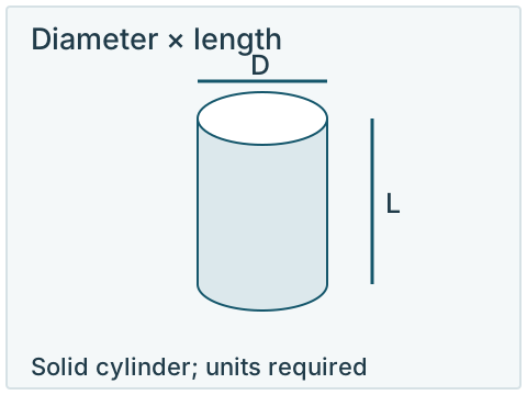
Define the cylinder by diameter and length
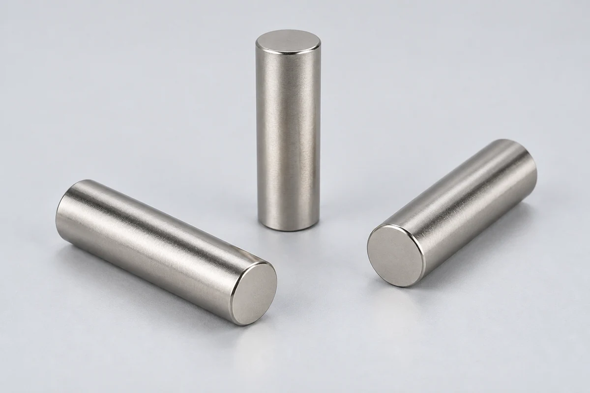
A solid cylinder needs two main dimensions: diameter D and axial length L. Include units and the tolerances that affect fit. “Disc”, “cylinder” and “rod” overlap in supplier catalogues; the dimensioned part is a more reliable specification than the name. A slender cylinder still needs its diameter and full axial length stated explicitly.[1] [2] [3]
For a short round part, the disc magnet guide covers diameter and thickness. A hollow cylinder needs outside diameter, bore and length; use the ring geometry guide as a starting point and identify a long tube separately. A mounting recess also needs its own countersunk hole section.
Locate the magnetic axis
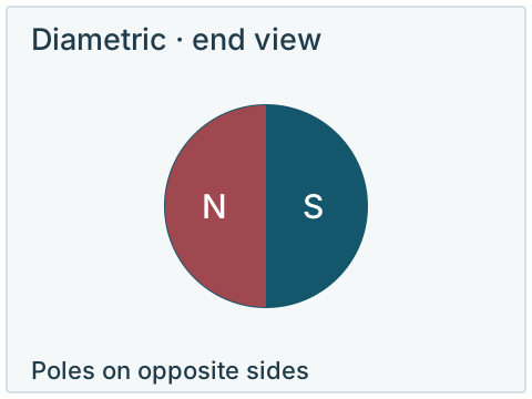
For a diametric cylinder, mark the magnetic axis in an end view and relate it to the assembly. The cylinder can fit mechanically while its poles face the wrong direction.
Open larger diagramWrite the dimension names next to the numbers. An entry such as “1 2 × 3” leaves the fraction, dimension order and units unresolved. A sketch with D and L avoids turning an ambiguous size into an incorrect order.
Match the poles to the assembly
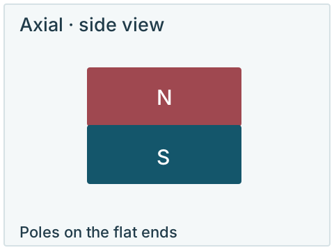
With axial magnetization, the two flat end faces are the north and south pole regions. With diametric magnetization, the pole regions are on opposite sides of the curved surface. A diametric cylinder viewed from its end is divided across a diameter; it is not an inner-versus-outer radial ring pattern.[1] [4] [5]
| Pattern | Pole location | Drawing instruction |
|---|---|---|
| Axial | Opposite flat end faces. | Name an end, such as face A, and specify its required pole. |
| Diametric | Opposite sides of the curved surface. | Mark the magnetic axis in an end view and relate it to an assembly reference. |
Describe both the axis and the required orientation
Axial
- Pole location
- Opposite flat end faces.
- Drawing instruction
- Name an end, such as face A, and specify its required pole.
Diametric
- Pole location
- Opposite sides of the curved surface.
- Drawing instruction
- Mark the magnetic axis in an end view and relate it to an assembly reference.
For a sensor or another orientation-sensitive assembly, keep the magnetic reference and the mechanical reference on the same drawing. Rotating a diametric cylinder changes its pole orientation in the installation. Confirm how that orientation will be located, retained or marked. See magnetization directions for other patterns.
Discuss the cylinder and its pole orientation
Nike Industrial Trading brings the cylinder drawing, magnetic orientation and purchasing questions into the same discussion. Start with a sketch or the available space if the dimensions are still open.
Share D × L, the pole requirement and how the cylinder fits into its assembly. If the application involves holding a load, include the mating material, contact or air gap and load direction. A catalogue pull-force result from another cylinder cannot establish your holding load; the pull-force guide explains the relevant test conditions.
Product: solid neodymium cylinder magnet
Diameter D / length L / units:
Finished tolerances / drawing revision:
Axial or diametric magnetization:
Required pole / orientation reference:
Grade / coating, if specified:
Temperature / environment / assembly gap:
Sample or order quantity:
Questions or acceptance requirements:
State whether the dimensions are for the finished coated part, particularly where a cylinder fits into a bore. Identify the critical fit and measurement method using the tolerance and inspection checklist. Material grade, coating, magnetic performance and availability need to be agreed for the proposed part; the illustration does not define a stocked size.
Use the form for your requirements, or send a drawing to [email protected] or WhatsApp. Add sample or order quantities to define the quotation request.
Request a cylinder magnet quoteTechnical sources
Read each source with its stated material, test conditions and publication scope.