
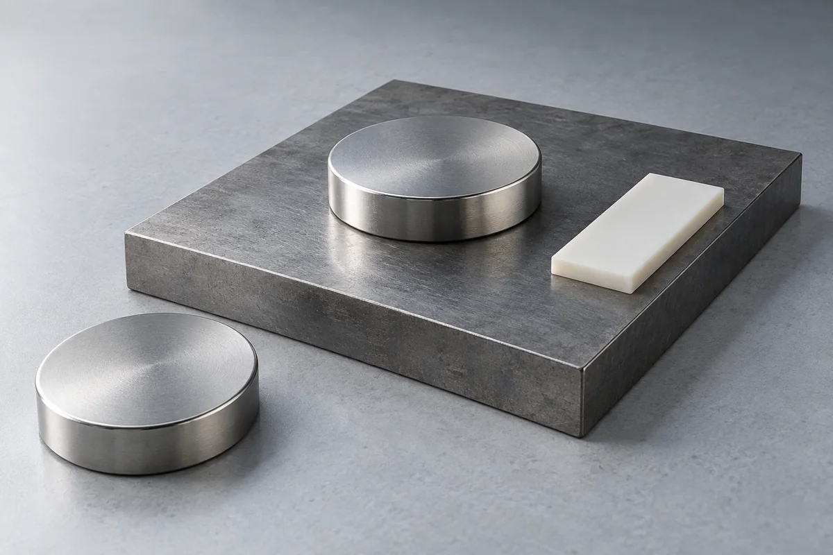
What a pull-force number measures
A typical catalogue pull value describes the force required to separate a magnet normally from a specified ferromagnetic target. It belongs to that setup. Adams describes a flat steel plate, full contact and a force gauge; supermagnete explains how its test and calculation procedures vary by geometry.[1] [2]
Identify whether a number is measured, calculated or supplied by another manufacturer. Also check whether it is a single magnet against steel, a magnet between steel pieces, or two magnets. K&J calls these Case 1, Case 2 and Case 3 respectively; those are its own useful labels, not a universal test-standard numbering scheme.[3]
| Configuration | What resists motion | What to verify |
|---|---|---|
| Normal pull-off | Attraction across the separation gap | Target, contact, alignment and loading |
| Sliding on a steel wall | Contact friction plus the actual magnetic/fixture arrangement | Surfaces, preload, friction and vibration |
| Tilt or peel | A changing contact and gap distribution | Lever arm, stiffness and attachment position |
| Two magnets moving sideways across a gap | A changing magnetic restoring force | Offset, gap and orientation; contact friction may be absent |
Similar-looking loads need different tests
Normal pull-off
- What resists motion
- Attraction across the separation gap
- What to verify
- Target, contact, alignment and loading
Sliding on a steel wall
- What resists motion
- Contact friction plus the actual magnetic/fixture arrangement
- What to verify
- Surfaces, preload, friction and vibration
Tilt or peel
- What resists motion
- A changing contact and gap distribution
- What to verify
- Lever arm, stiffness and attachment position
Two magnets moving sideways across a gap
- What resists motion
- A changing magnetic restoring force
- What to verify
- Offset, gap and orientation; contact friction may be absent
Keep steel and gaps in the specification
Thin steel can limit the magnetic circuit differently from a thick test plate. Steel grade, target area, flatness and surface condition matter. Paint, plastic, paper, rust and an adhesive layer can all create separation or prevent full contact. A curved target may leave part of a flat magnet unsupported.
Consequently, a contact rating cannot be converted into performance at a specified gap by a universal percentage. Nor does doubling the grade number, thickness or contact area produce a universally proportional force change. Evaluate the actual geometry and target.[5]
For example, “a magnet for a 2 mm plastic cover over a painted steel panel” describes two gap contributors and a target condition. It is a much better starting specification than “a 10 kg magnet”. The required direction of force and panel details still need to be added.
Do not use one shear percentage for every application
A magnet sliding while pressed against steel depends on the actual friction coefficient and the arrangement that supplies normal force. Lubrication, fingerprints, surface wear or vibration can change the result. A nominal pull value does not establish that coefficient.[1]
Non-contact sideways movement between two magnets is different. K&J’s door experiment investigates magnetic restoring force across a gap while explicitly ignoring friction. Its measured ratios should not be transferred to a magnet carrying a load on a vertical wall.[4]
Use a mechanically defined assembly test when sliding, peeling or vibration is relevant. Plan retention for the consequences of release rather than relying on an optimistic contact measurement.
Write a repeatable force acceptance requirement
- Name the magnet or assembly, material state and drawing revision.
- Define target steel, dimensions, surface and the intended gap.
- Specify magnet orientation, fixture alignment and load direction.
- State loading rate, temperature, repetitions and reporting method.
- Set the required result and any post-test inspection.
Calculators can help compare early design choices, but their geometry and boundary assumptions need checking. K&J explicitly treats its tool as approximate and requires testing in the application.[6]
A breakaway-force figure is not a rated lifting capacity. Lifting, overhead retention and other safety-critical uses require a suitable engineered system, applicable requirements and qualified validation. A single universal derating factor cannot turn a bare magnet’s catalogue pull value into an approved lifting device.
Technical sources
Source material has its own scope and conditions. These references explain technical choices; they are not evidence of our stock, certifications or supplied products.
- Adams Magnetic Products: Pull-force measurement and installation conditions
- Webcraft / supermagnete: Adhesive-force measurement procedures
- K&J Magnetics: Magnet strength test procedures
- K&J Magnetics: Non-contact shear-force experiment
- Dura Magnetics: Magnetic pull force in practical applications
- K&J Magnetics: Magnet calculator scope and assumptions