
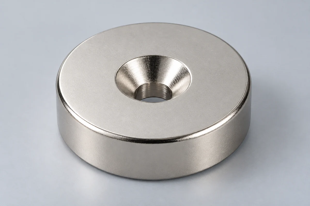
Identify the construction before ordering
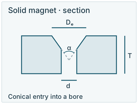
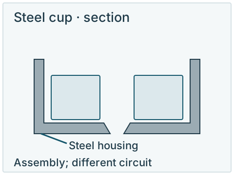
A solid countersunk magnet has the mounting hole formed in the magnetic body itself. In a countersunk pot or cup magnet, a magnet works as part of an assembly with a steel housing. The housing, contact surface and magnetic circuit change the installation and force rating. The two constructions should not share an assumed holding-force value.[1] [3]
Check a section view or product drawing for the magnetic material, surrounding steel and hole location. A silver outer surface alone is not enough to identify the construction. This page addresses solid countersunk parts; identify a steel-cup assembly explicitly when you send a requirement.
Specify the hole and the finished magnet
Describe the outside shape and the hole independently. A countersink has a conical entrance. Its entrance diameter, through-hole diameter and angle or depth must fit the intended screw head and leave the required magnet section. A screw designation on its own does not establish that fit.[1] [2] [5]
| Feature | Round or ring-like part | Block or square part |
|---|---|---|
| Outside dimensions | Outside diameter and axial thickness. | Length, width and thickness. |
| Hole section | Through-bore diameter, entrance diameter, countersink angle or depth. | The same section details for each mounting hole. |
| Hole location | Centre location or any required offset. | Hole centres, spacing and the reference edges. |
| Faces and poles | Recess on one or both faces; required pole on the named face. | Recess face, magnetic axis and pole orientation in the assembly. |
| Finished fit | Coating allowance, screw-head seating and critical tolerances. | Coating allowance, head clearance and critical tolerances. |
Geometry that belongs on the drawing
Outside dimensions
- Round or ring-like part
- Outside diameter and axial thickness.
- Block or square part
- Length, width and thickness.
Hole section
- Round or ring-like part
- Through-bore diameter, entrance diameter, countersink angle or depth.
- Block or square part
- The same section details for each mounting hole.
Hole location
- Round or ring-like part
- Centre location or any required offset.
- Block or square part
- Hole centres, spacing and the reference edges.
Faces and poles
- Round or ring-like part
- Recess on one or both faces; required pole on the named face.
- Block or square part
- Recess face, magnetic axis and pole orientation in the assembly.
Finished fit
- Round or ring-like part
- Coating allowance, screw-head seating and critical tolerances.
- Block or square part
- Coating allowance, head clearance and critical tolerances.
A ring-like countersunk part needs a section showing how the conical recess joins the bore. For a square or rectangular part, include the hole position as well as its section. Use the block or disc guide for the outside dimensions, then add the mounting features.
There is no universal screw angle or tightening torque for every solid magnet. Supply the screw drawing or applicable screw standard together with the magnet drawing, so the head shape and seating arrangement can be checked for that combination.[1] [4]
Check the head, not only the thread size
Imagine a drawing with a 90° included countersink, while the intended screw drawing specifies an 82° head. These are hypothetical drawing inputs, not a recommended screw standard or product size. Even if the threaded shank fits through the bore, the conical surfaces do not match. The head may contact locally or protrude rather than seat as intended.
Check the head angle, entrance diameter, recess depth, remaining magnet section and the required flushness together. Resolve the mismatch in the drawings before assembly; tightening harder cannot correct incompatible geometry.
Discuss the magnet and its mounting detail
Bring the magnet section and intended screw-head drawing to Nike Industrial Trading. We keep the outside geometry, mounting hole and pole requirement with the quantity and documents needed for your quotation request.
Sintered NdFeB is brittle. An uneven support surface, an incompatible screw head or forcing the part into place can concentrate stress around the hole and damage it. Plan the support and retention arrangement for the finished part. Use controlled assembly procedures established for that assembly rather than using the screw to correct a misfit.[1]
Construction: solid magnet / steel-cup assembly
Outside dimensions / units / drawing revision:
Through-hole and countersink section:
Hole positions / recessed face(s):
Screw-head drawing or standard:
Magnetic axis / required pole face:
Coating / support surface / environment:
Load direction / contact or air gap:
Sample and order quantities:
Installation or inspection questions:
The handling guide covers brittle-part precautions, and the inspection guide helps define finished hole and surface checks. For bulk purchasing, add quantities and packaging requirements. Confirm the particular construction, screw fit and test conditions before relying on a holding-force rating.
Send the drawing and screw-head reference to [email protected] or WhatsApp, or start with the online inquiry below.
Request a countersunk magnet quoteTechnical sources
Read each source with its stated material, test conditions and publication scope.