
Shapes and finished dimensions
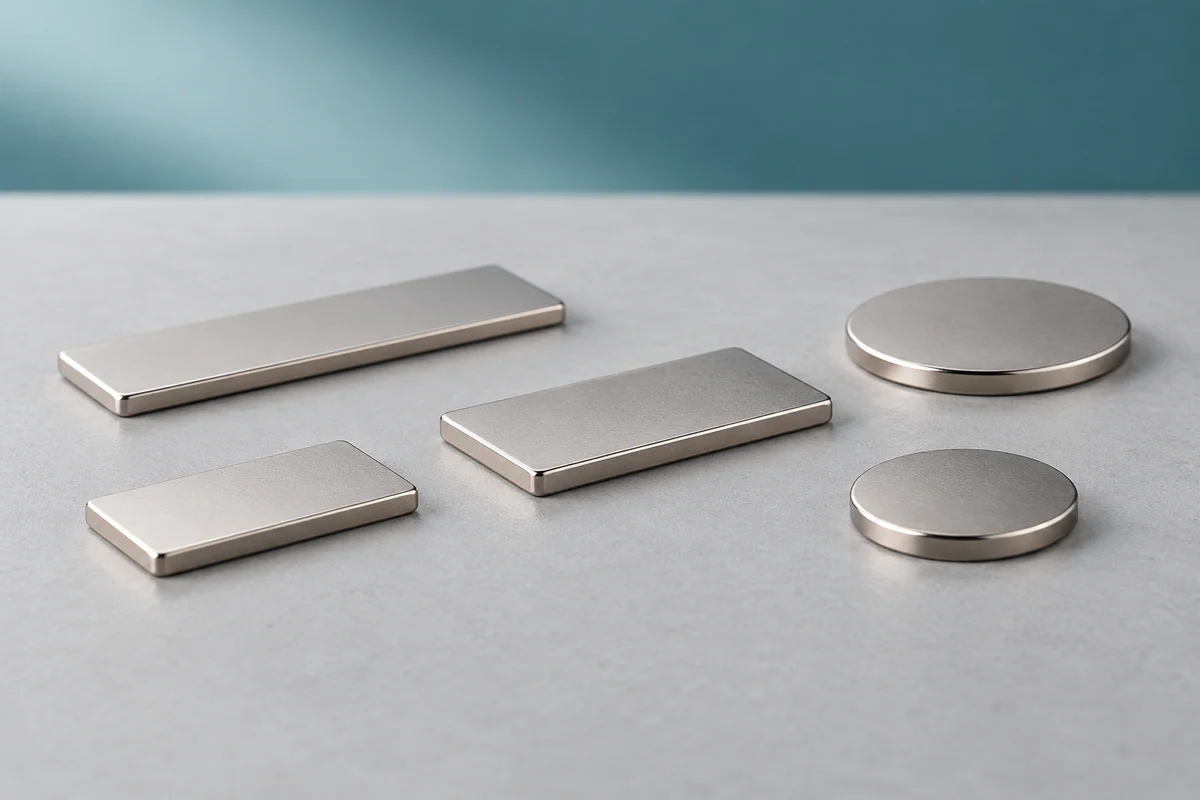
Thin neodymium discs fit round recesses, flat blocks follow rectangular pockets, and rings leave a central opening. They are used in slim covers and compact sensing assemblies where the magnet has little room behind the surface.
A cover needs enough retention to stay closed and an opening force the user can manage. A sensor needs a field within its specified range at the chip. Decide which result you need before choosing the grade. To check fit, use the finished thickness and tolerance: “thin” alone gives no dimensional limit.
Describe the part you need
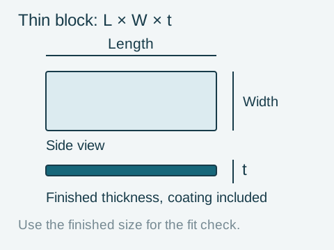
For a disc, give diameter × finished thickness; for a block, length × width × finished thickness; for a ring, outside diameter × inside diameter × finished thickness. Include units and mark the magnetic axis separately. State whether the dimensions include the coating.
Thin magnet configurations to discuss
These example specifications give you a starting point for an enquiry. Choose the outline that fits your assembly, then compare thickness, material and surface protection. We confirm the final specification and availability in the quotation.
| Disc dimensions | Grade and finish | Magnetization |
|---|---|---|
| 10 mm diameter × 1 mm thick | N35, Ni-Cu-Ni coating | Through thickness, with poles on the two flat faces |
| 25.4 mm diameter × 0.794 mm thick (1-inch diameter × 1/32-inch thickness) | N52, Ni-Cu-Ni coating | Through thickness, with poles on the two flat faces |
Example specifications for thin discs
10 mm diameter × 1 mm thick
- Grade and finish
- N35, Ni-Cu-Ni coating
- Magnetization
- Through thickness, with poles on the two flat faces
25.4 mm diameter × 0.794 mm thick (1-inch diameter × 1/32-inch thickness)
- Grade and finish
- N52, Ni-Cu-Ni coating
- Magnetization
- Through thickness, with poles on the two flat faces
The wider disc occupies more face area despite being thinner. Neither size has a single holding-force value that applies to every installation: the gap, target and direction of loading matter. For a rectangular recess or a central opening, send the block or ring dimensions you need.
From your enquiry to a quotation
Nike Industrial Trading brings your magnet requirements together for sourcing and quotation. Send a drawing and revision, or photos of an existing part with measured dimensions. For a new design, start with a sketch of the available space, the magnet's job and approximate quantity. We help clarify the dimensions, material, finish and supply options; you can leave the grade or coating undecided in your first message.
Check the quotation against the drawing or agreed specification, including finished thickness, tolerance, magnetic axis, material and finish. Confirm the quantity, price and delivery terms before ordering. If you need samples or product documents, ask us to confirm their availability and what they cover for the proposed item.
Download the thin magnet specification worksheet (TXT). Fill in what you know and keep open questions with the drawing. A short message is also enough to start.
Fit and retention in a slim cover
In this example, a 1.00 mm finished magnet sits between a 0.15 mm rear adhesive layer and a 0.50 mm nonmagnetic front cover. The stack occupies 1.65 mm before clearance or dimensional variation. A 1.65 mm pocket would leave no allowance for a thicker delivered part or bond line.
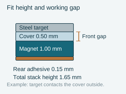
When the steel target touches the outside of the cover, it remains 0.50 mm away from the magnet. The rear adhesive adds to the stack height but is outside this front gap. A recessed magnet, paint or imperfect contact can add further separation. Check that separation before comparing a catalogue contact-pull value with the installed result.
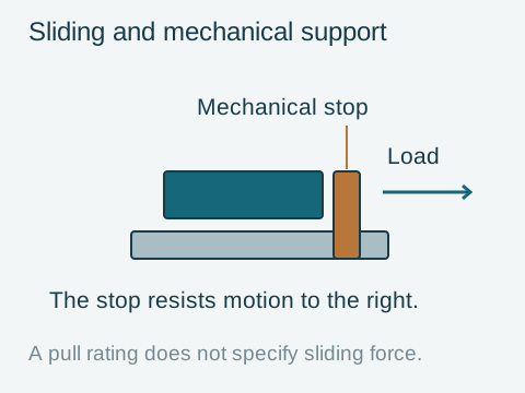
A cover can resist opening yet slide sideways in use. A pocket or stop can carry the sliding load while the magnet holds the cover closed. Size and position that support for the load it must carry. Chipped edges during installation also point to a need to review support, collisions and assembly stress.
| Observed problem | First checks | Result to verify |
|---|---|---|
| The cover will not sit flush | Maximum finished thickness, adhesive thickness, cover and pocket depth | Assembly clearance across the specified dimensional ranges |
| The cover opens too easily | Front gap, steel target, pole orientation and opening direction | Retention in the complete cover assembly |
| The cover slides sideways | Mechanical location, friction and any stop or pocket | Resistance to the actual sliding load |
| Edges chip during installation | Unsupported areas, force fits, collisions and clamping pressure | An assembly method that supports the brittle part |
Troubleshooting fit, retention and damage
The cover will not sit flush
- First checks
- Maximum finished thickness, adhesive thickness, cover and pocket depth
- Result to verify
- Assembly clearance across the specified dimensional ranges
The cover opens too easily
- First checks
- Front gap, steel target, pole orientation and opening direction
- Result to verify
- Retention in the complete cover assembly
The cover slides sideways
- First checks
- Mechanical location, friction and any stop or pocket
- Result to verify
- Resistance to the actual sliding load
Edges chip during installation
- First checks
- Unsupported areas, force fits, collisions and clamping pressure
- Result to verify
- An assembly method that supports the brittle part
Thickness, area and grade
Once the stack fits, compare alternatives within the dimensions you can change. Test them against the same retention or sensing requirement, recording any changes to the gap, target or mounting.
| Design constraint | Options to compare | What to verify |
|---|---|---|
| Thickness is fixed; footprint can change | Alternative outlines and face areas within the available space | Retention or sensor field with the actual counterpart, gap and pole orientation |
| Footprint is fixed; thickness can change | Different thicknesses, keeping the magnetic axis explicit | The complete height stack and installed magnetic result |
| The magnet outline is fixed | Working gap, target material and target geometry where the assembly allows changes | Output in each proposed circuit; if the circuit is also fixed, compare suitable grades within it |
| Temperature duty changes | Material data and the magnetic circuit at the required temperature | Required output while hot and permitted loss after cooling |
What can change within the available space?
Thickness is fixed; footprint can change
- Options to compare
- Alternative outlines and face areas within the available space
- What to verify
- Retention or sensor field with the actual counterpart, gap and pole orientation
Footprint is fixed; thickness can change
- Options to compare
- Different thicknesses, keeping the magnetic axis explicit
- What to verify
- The complete height stack and installed magnetic result
The magnet outline is fixed
- Options to compare
- Working gap, target material and target geometry where the assembly allows changes
- What to verify
- Output in each proposed circuit; if the circuit is also fixed, compare suitable grades within it
Temperature duty changes
- Options to compare
- Material data and the magnetic circuit at the required temperature
- What to verify
- Required output while hot and permitted loss after cooling
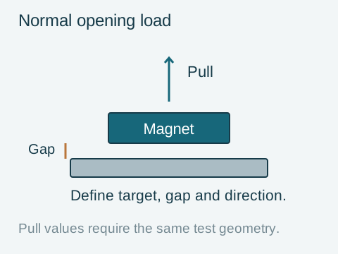
N52 is a material grade; the holding force still depends on the target, gap, pole arrangement and test direction. For a sensing assembly, use the field range specified for the sensor at its installed position.
Check the temperature duty separately. A thin magnet's proportions and the surrounding steel affect how it behaves when hot. Specify the required output at temperature and any permitted loss after cooling.
How thickness and the magnetic circuit affect temperature performance
For a thin, wide part magnetized through its thickness, the short magnetic length can give a lower permeance coefficient (Pc) than a longer part along the magnetic axis. Pc helps locate the magnet's working point on its demagnetization curve. This comparison assumes a magnet in free space, without an effective external return path. Nearby steel or other magnets can change that working point. Assess the actual circuit using curves for the required temperature.
Mounting and edge protection
Sintered NdFeB is hard and brittle. A flat supporting surface reduces the need for a thin part to span a recess or carry bending loads. Put holes, edge details and any machining requirements on the drawing before supply; finishing a sintered magnet requires specialist processes.
For adhesive mounting, consider the selected finish, adhesive system, bond-line space, curing conditions and environment together. An adhesive thickness chosen to fill a recess also changes the stack height. Mechanical retention needs its own tolerance and stress assessment, particularly where a clip or screw loads an edge.
Keep parts separated during assembly and plan how they will be moved into position. Colliding magnets can chip or fracture.
Shapes and ordering questions
When comparing thin discs, check the grade, magnetization and tolerances alongside the dimensions. The disc, block and ring guides cover the dimensions for each outline. A flat pot magnet includes a steel housing, so its overall height and mounting arrangement must cover the whole assembly.
Can I enquire about a 1 mm magnet without choosing a grade?
Yes. Send the outline, available height, application and approximate quantity, with a sketch or photo if you have one. We will identify the remaining product details needed for a quotation.
Can I stack thin magnets to make a thicker part?
Yes. Magnets of the same grade and matching cross-section, magnetized through their thickness and stacked with opposite poles touching, can behave approximately like a single magnet of the combined thickness. The pull force does not increase by a fixed amount per layer. Coatings and any adhesive between the magnets add internal separation, and the stack needs secure alignment and retention. Check its total height and installed field or force in the intended assembly.
Request a thin magnet quote
Tell us how much space is available and whether the main question is fit, retention or mounting. You can send the drawing later if it is still being prepared.
Thin magnet enquiry: start with what you know
Application and required result:
Shape / available space, with units:
Approximate quantity:
Sketch, photo or drawing available? Any open question:
Details to confirm before ordering
Finished thickness and tolerance; drawing revision; cover and adhesive dimensions; target and working gap; magnetic axis; temperature and environment; coating; requested sample checks and production quantity. Your design team should validate fit, mounting and magnetic performance in the intended assembly before approving the part for use.